• DE
  • Lösungen
    • Fire Protection Bonnets

      Fire Protection Bonnets

      • Copy-Cap WV
      • Copy-Cap WH
    • Fire protection curtains

      Fire protection curtains

      In case of fire, fire protection curtains close wall and ceiling openings. Their construction (roll-down or folding technique) and the use of different fabrics provide for a wide range of applications as well as different protection goals, classifications and time classes. The casing and guide rails of the highly flexible systems blend almost invisibly into the building and allow plenty of scope for sophisticated architecture and open room concepts.

      • Fibershield®-P
      • Fibershield®-E
      • Fibershield®-I
      • Fibershield®-HC
      • Fibershield®-S
      • Fibershield®-F
    • Conveyor system closures

      Conveyor system closures

      Various production and logistics processes call for the most diverse types of conveyor systems. If these conveyor lines pass through fire-retardant or fire-resistant walls or ceilings, the openings required for this purpose must be provided with fire protection closures to prevent the spread of fire through the conveyor system or the goods conveyed. In the event of fire, conveyor system closures (CSC for short) must close these openings immediately and automatically. Fire resistance classified according to DIN EN 13501-2 is just as important as the smooth clearance of the closing areas in the event of a fire.

      • ECClos®-S
      • ECClos®-Q
      • ECClos®-FLEX-I
      • Ecotube
      • GCC
      • BR100
    • Smoke curtains

      Smoke curtains

      A smoke apron is a part of a smoke control system which also includes other components such as natural smoke and heat exhaust ventilators (EN 12101-2) and mechanical smoke and heat exhaust ventilators (EN 12101-3). Smoke aprons restrict the movement of combustion gases within a building in case of fire.

      • Supercoil
      • Stripecoil
      • Smokeshield-S
      • Fixed smoke apron
    • Smoke protection curtains

      Smoke protection curtains

      Once closed, smoke protection curtains (SPC) restrict the passage of smoke during the phase of fire formation, so that in the event of a fire, there is enough time to rescue people and animals from the room behind the curtain and to recover material assets without the need for respiratory equipment.

      • Fiberseal
    • Gates

      Gates

      The solution for issues with fire protection dampers in ventilation and air conditioning systems in conveyor processes. Stöbich offers fire protection for pneumatic conveyor lines the closing elements of which are not exposed to the flow of conveyed material. This way, the closing element cannot be damaged or contaminated by abrasive conveyed goods.

      • Omnicompact
    • Control units

      Control units

      Each automatic fire protection system needs a control unit. They are critical to safety, because a failure of this function means that the entire investment into a fire protection sealing has been in vain. Control units coordinate both fire detection and interaction with other control units, such as higher-level building control systems or clearing of the closing area of conveyor system closures.

      • RZ7
      • RZ3/4
      • RZ8
      • Battery system
      • Movipower 350/550
      • UPS
      • FFE-KDR
    • Special Solutions
      • ECClos®-D
      • ECClos®-K
      • Universal-B
      • Universal-S
      • ECClos®-FLEX
      • Collar
      • Turbocoil
      • Omnitube
    • Technical Fire Protection
      • Fire Multi Detektor
    • Fire protection for battery storage
      • Strainbox XS
      • Strainbox S
      • Strainbox L
      • Strainbox XL
      • Strainlock
      • Packaging Cushions
    • Service
  • Referenzen
  • Themenwelten
  • Weltmarktführer
  • Nachhaltigkeit
  • News
  • Jobs
  • Kontakt

SYSTEM: FIBERSHIELD® | BAUREIHE: FIBERSHIELD®-I

  • Fibershield-I

Produktbeschreibung

Im Alarmfall selbstschließender, wärmedämmender Feuerschutzabschluss textiler Bauweise in vertikaler Einbaulage und Schließrichtung.

BauartWärmedämmender Feuerschutzabschluss textiler Bauweise
NachweisCE Kennzeichnung gemäß EN 16034:2014 in Verbindung mit EN 13241:2003+A2:2016
Schließrichtungvon oben nach unten
FeuerwiderstandEI1 30 – EI2 120 | geprüft nach EN 1634-1:2014-03 | klassifiziert nach EN 13501-2:2016
RauchschutzSa: für die Fugenlänge 14,5 m für EI1 30 – EI2 120 | geprüft nach EN 1634-3:2005-01 in Verbindung mit EN 1363-1:2012-10 | klassifiziert nach EN 13501-2:2016
SchließzyklenC0, C1, C2 | geprüft nach EN 12605:2000-08 | klassifiziert nach EN 13501-2:2016
Brandverhalten des TextilsB-s1, d0; E-d2 | geprüft nach ISO 11925-2 und EN 13823 | klassifiziert nach EN 13501-1:2018
UmweltbedingungenNicht berücksichtigt sind besondere Umweltbedingungen (z.B. Luftfeuchtigkeit > 80%, Umgebungstemperatur < 5°C und > 45°C, Windlasten, etc.)
Sichtbare Oberflächenverzinkt | RAL, glatt, seidenglänzend, Standardfarbton | Edelstahl Typ I V2A Werkstoff A-1.4301 (blank) | Edelstahl Typ II V2A Werkstoff A-1.4301, K240 (geschliffen) | jeweils für die sichtbaren Flächen des Gehäuses und der Führungsschienen
FiberShield-I Stöbich

Legende Systemkomponenten:
1 = Rauchmelder
2 = Gehäuse
3 = Führungsschiene
4 = Ansteuerungsmodul
5 = Auslösevorrichtung (Ausführungsdetails der elektrischen Komponenten sind der gültigen allgemeinen Bauartgenehmigung der Feststellanlage zu entnehmen.)

Legende Vermaßung:
Baukörper
B = lichte Rohbauhöhe
A= lichte Rohbaubreite
System
AY = Systemhöhe
LH = lichte Systemhöhe
LB = lichte Systembreite
BJ = Systembreite
Gehäuse
BX = Tiefe
BW = Höhe
v = Versatz zwischen Führungsschiene und Gehäuse
Führungsschiene
CD = Breite
CE = Tiefe
BD = Versatz links
BE = Versatz rechts

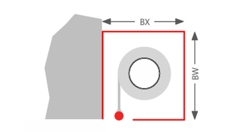
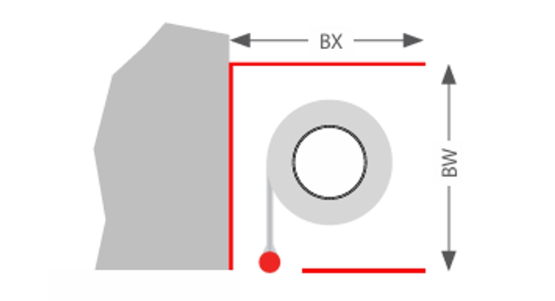
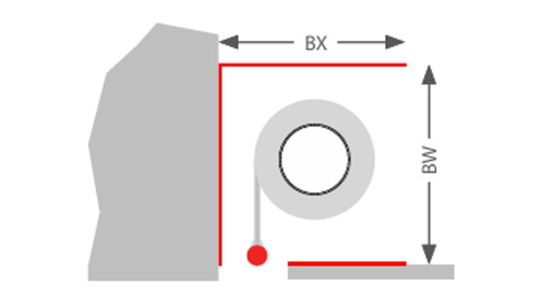
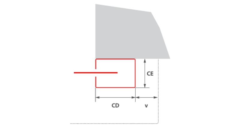
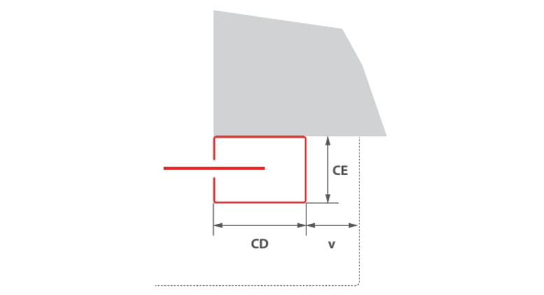
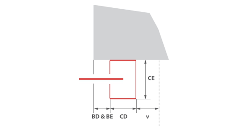
Größenabmessungen und Systemaufbau

Durch die Kombination von Klassifizierungen oder das Verhältnis von lichter Systembreite zu lichter Systemhöhe können sich die genannten Maximalabmessungen reduzieren und die Abmessungen des Gehäuses und der Führungsschienen können variieren. Es gelten die Angaben auf dem Angebot.

Feuerwiderstandsklasse/
Klassifizierungen
Größe** [y x r] in mmGewebeWandstärke* in mmGehäuseFührungsschiene [a(+c) x b]
EI1 30/EI2 307315 x 3800Stratex 3150Typ ATyp 1 oder Typ 3***
EI1 30/EI2 307315 x 4950Stratex 3150Typ BTyp 1 oder Typ 3***
EI1 606600 x 4840Stratex 12150Typ BTyp 2
EI2 604400 x 3400Stratex 6150Typ ATyp 1 oder Typ 3***
EI2 604400 x 4400Stratex 6150Typ BTyp 1 oder Typ 3***
EI2 606600 x 4840Stratex 9150Typ BTyp 1
EI1 906000 x 4400Stratex 12150Typ BTyp 2
EI2 906000 x 4400Stratex 9150Typ BTyp 1
EI2 1206000 x 4840Stratex 12175Typ BTyp 2
SaSa = Fugenlänge darf 14,5 m (normativ: 3-seitig ohne Abschlussleiste) nicht überschreiten
C7315 x 4950Stratex 3, EI1 30/EI2 30
C14400 x 4400Stratex 6, EI1 60
6000 x 4400Stratex 9, EI2 60
6000 x 4400Stratex 9, EI2 90
C26600 x 4840Stratex 3, EI1 30/EI230
6600 x 4400Stratex 12, EI1 60/EI260
6600 x 4400Stratex 12, EI1 90

Die Einbausituation muss den baurechtlichen Anforderungen des Einbaulandes entsprechen. Die Feuerwiderstandsfähigkeit einer Decken- oder Wandtragkonstruktion und der angrenzenden Bauteile muss mindestens der des Feuer- und /oder Rauchschutzabschlusses/ Feuer- und /oder Rauchschutzvorhangs entsprechen. Der Nachweis der Standsicherheit und Gebrauchstauglichkeit der angrenzenden Wände und Bauteile muss unter allgemeinen Umgebungsbedingungen und im Brandfall gegeben sein. Siehe auch Hinweise zur Norm-Tragkonstruktion in der EN1366-7:2004 beziehungsweise EN1363-1:2020. Das Brandschutzsystem darf auch im Brandfall außer dem Eigengewicht keiner zusätzlichen Belastung ausgesetzt sein.
* Abweichungen von Größenabmessungen auf Anfrage
** geprüfte Wandarten nach der Einbauanleitung
*** Führungsschienen Typ 3 maximale Größe 3000 x 2870 mm und keine Dauerfunktionen C1 & C2

Gehäuse


Wand mit Gehäuseblende
Typ A: BX = 380 mm, BW = 350 mm
Typ B: BX = 460 mm, h = 430 mm
Wand ohne Gehäuseblende
Typ A: BX = 380 mm, BW = 350 mm
Typ B: BX = 460 mm, BW = 430 mm
Wand ohne Gehäuseblende, mit Unterdecke
Typ A: BX = 380 mm, BW = 350 mm
Typ B: BX = 460 mm, BW = 430 mm

Führungsschienen


Typ 1
Typ 1 (Wandmontage)
CD = 200 mm
CE = 82 mm
v = 47 mm
Typ 2
Typ 2 (Wandmontage)
CD = 230 mm
CE = 110 mm
v = 42 mm
Typ 3
Typ 3 (Wandmontage)
CD = 90 mm
CE = 120 mm
v = 77 mm

BD & BE = 0 mm für EI1 30, EI2 30
BD & BE = 60 mm für EI2 60