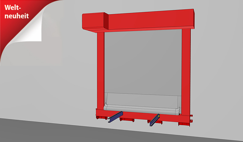
SYSTEM: ECCLOS® | Baureihe: Ecclos®-Flex-I
| Bauart | Feuerschutzabschluss im Zuge bahngebundener Förderanlagen |
| Nachweis | ETA-21/0359 | VKF Anerkennung Nr. 32476 |
| Schließrichtung | von oben nach unten |
| Feuerwiderstand | EI2 90 | geprüft nach DIN EN 1366-7:2004-09 | klassifiziert nach EN 13501-2:2007 |
| Schließzyklen | C | geprüft nach EN 12605:2000-08 | klassifiziert nach EN13501-2:2016 für planmäßig offene Abschlüsse |
| Wiederöffnung | motorisch |
| Fördersystem | Rollenbahnen | Gurtförderer | Tragkettenförderer |
| Sichtbare Oberflächen | Abdeckung, Führungsschienen und Wickelgehäuse Edelstahl 1.4301 (V2A) beschichtet in RAL Farbton Festfeld unbehandelte Brandschutzplatten gestrichen mit Dispersionsfarbe in RAL ähnlichem Farbton Blechverkleidung Edelstahl 1.4301 (V2A) Blechverkleidung beschichtet in RAL Farbton |
Downloads
Größenabmessungen und Systemaufbau
Durch die Kombination von Klassifizierungen oder das Verhältnis von lichter Systembreite zu lichter Systemhöhe können sich die genannten Maximalabmessungen reduzieren und die Abmessungen des Gehäuses und der Führungsschienen können variieren. Es gelten die Angaben auf dem Angebot.
| Bauteil (Tragkonstruktion), in welches der Abschluss eingebaut werden darf | erreichbare Feuerwiderstandklasse | |||
| lichte Wandöffnungsbreite | ||||
| massive Wand hoher Dichte, Mauerwerk oder Massivbeton mit Gesamtdichte von ≥ 800 kg/m3 und einer Dicke ≥ 150 mm | EI2 90 | ab 500 mm bis 6.000 mm | ab 500 mm bis 4.400 mm | |
| massive Wand niedriger Dichte, Porenbeton mit Gesamtdichte von ≥ 450 kg/m3 und einer Dicke ≥ 150 mm | EI2 90 | ab 500 mm bis 6.000 mm | ab 500 mm bis 4.400 mm | |
Die Einbausituation muss den baurechtlichen Anforderungen des Einbaulandes entsprechen. Die Feuerwiderstandsfähigkeit einer Decken- oder Wandtragkonstruktion und der angrenzenden Bauteile muss mindestens der des Feuerschutzabschlusses entsprechen. Der Nachweis der Standsicherheit und Gebrauchstauglichkeit der angrenzenden Wände und Bauteile muss unter allgemeinen Umgebungsbedingungen und im Brandfall gegeben sein. Siehe auch Hinweise zur Norm-Tragkonstruktion in der EN1366-7:2004 beziehungsweise EN1363-1:2020. Das Brandschutzsystem darf auch im Brandfall außer dem Eigengewicht keiner zusätzlichen Belastung ausgesetzt sein.
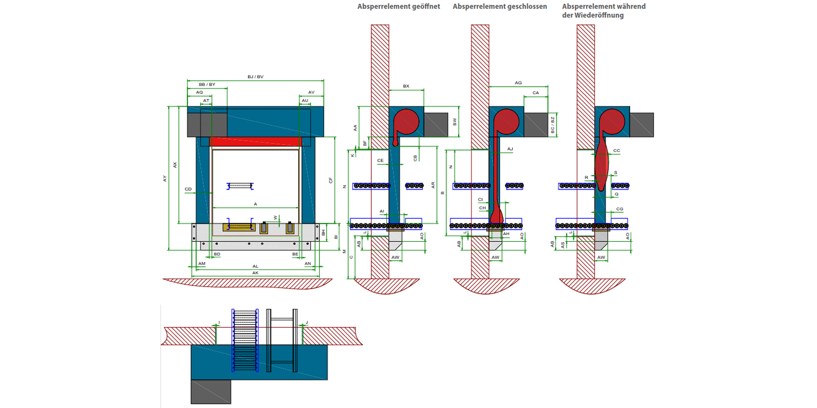
Schließrichtung vertikal von oben nach unten
| A- Lichte Wandöffnungsbreite | 500 mm bis 6000 mm |
| B - Lichte Wandöffnungshöhe | 500 mm bis 4400 mm |
| C - Unterkante Wandöffnung | 0 - n |
| I - Planungszuschlag links | Defaultwert 20 mm |
| J - Planungszuschlag rechts | Defaultwert 20 mm |
| K - Planungszuschlag oben | Defaultwert 20 mm |
| L - Planungszuschlag unten | Wandhängendes System: Defaultwert = 20 mm bodenstehendes System: Defaultwert = 0 mm |
| Q - Fördertechniktrennstelle Breite | abhängig von Position und Typ der Fördertechnik und Größe der Lichten Wandöffnungsmaße |
| R - Fördertechniktrennstelle Maß Wandseite | abhängig von Position und Typ der Fördertechnik und Größe der Lichten Wandöffnungsmaße |
| S - Fördertechniktrennstelle Maß Raumseite | abhängig von Position und Typ der Fördertechnik und Größe der Lichten Wandöffnungsmaße |
| N - Durchfahrtshöhe/Durchgangshöhe | abhängig von Position und Typ der Fördertechnik und Größe der Lichten Wandöffnungsmaße |
| M - Förderniveau | 0 - n |
| W - Förderniveauüberstand | bis +25 mm |
| AA - Platzbedarf oberhalb der Öffnung | BF + BW + K ungetrennt durchlaufende Fördertechnik = 200 mm + 430 mm + 20 mm = 650 mm getrennte Fördertechnik = 50 mm + 430 mm + 20 mm = 500 mm |
| AB - Platzbedarf unterhalb der Öffnung | mit Festfeld = L + AS + AO = 20 mm + 80 mm + 120 mm = 220 mm ohne Festfeld = 0 mm |
| AG - Platzbedarf Antrieb Einbauseite | 800 mm |
| AH - Abschottungstiefe am Absperrelement | 150 mm |
| AI - Abschottungstiefe am Festfeld | 175 mm |
| AJ - Dicke Absperrelement | ca. 12 mm |
| AK - Festfeldgesamtbreite | AL + AM + AN |
| AL - Festfeldbreite | A + I + J + CD + CD = A + 20 mm + 20 mm + 230 mm + 230 mm = A + 500 mm |
| AM - Befestigungsüberstand Festfeld links | 50 mm |
| AN - Befestigungsüberstand Festfeld rechts | 50 mm |
| AO - Befestigungsüberstand Festfeld unten | 120 mm |
| AQ - Platzbedarf Wandrahmen links neben der Öffnung | I + BD + CD + 100 mm = 20 mm + 50 mm + 230 mm + 100 mm = 400 mm |
| AR - Verfahrweg Absperrelement / Abrolllänge | = N |
| AS - Überdeckung Festfeld unten | 80 mm |
| AT - Überdeckung Absperrelement link | 215 mm |
| AU - Überdeckung Absperrelement rechts | 215 mm |
| AV - Platzbedarf Wandrahmen rechts neben der Öffnung | J + BE + CD + 100 mm = 20 mm + 50 mm + 230 mm + 100 mm = 400 mm |
| AW - Festfeldtiefe | 175 mm |
| AX - Höhe Wandrahmen | N + AA ungetrennt durchlaufende Fördertechnik = N + 650 mm getrennte Fördertechnik = N + 500 mm |
| AY - Systemhöhe | BI + AX |
| BB - Antriebstechnik Breite | 750 mm |
| BC - Antriebstechnik Höhe | 430 mm |
| BD - Versatz links | 50 mm |
| BE - Versatz rechts | 50 mm |
| BF - Versatz oben | ungetrennt durchlaufender Fördertechnik = 200 mm getrennte Fördertechnik = 50 mm |
| BH - Festfeldhöhe | M - C + L + AS |
| BI - Festfeldgesamthöhe | BH + AO |
| BJ - Systembreite | AQ + AV + A = 400 mm + 400 mm + A |
| BV - Wickelgehäuse Breite | = BJ |
| BW - Wickelgehäuse Höhe | 430 mm |
| BX - Wickelgehäuse Tiefe | 460 mm |
| BY - Antriebsgehäuse Breite | 750 mm |
| BZ - Antriebsgehäuse Höhe | 430 mm |
| CA - Antriebsgehäuse Tiefe | 340 mm |
| CB - Parkbereich Absperrelement unter Wickelgehäuse | ungetrennt durchlaufende Fördertechnik = 200 mm getrennte Fördertechnik = 0 mm |
| CC - Dicke Absperrelement bei Wiederöffnung | 400 mm |
| CD - Führungsschiene Breite | 230 mm |
| CE - Führungsschiene Tiefe | 114 mm |
| CF - Führungsschiene Höhe | AX - BW |
| CG - Trennstelle Fördertechnikführung Breite | 300 mm |
| CH - Trennstelle Fördertechnikführung Maß Wandseite | 0 mm |
| CI - Trennstelle Fördertechnikführung Maß Raumseite | 300 mm |
| CJ - Verhältnis Breite/Höhe | BJ/CF >= 0,333 |