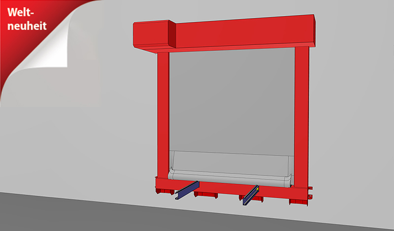
SYSTEM: ECCLOS® | Series: Ecclos®-Flex-I
| Type | Fire protection closure in the course of railway-bound conveyor systems |
| Verification | ETA-21/0359 | VKF approval no. 32476 |
| Closing direction | from top to bottom |
| Fire resistance | EI2 90 | tested according to DIN EN 1366-7:2004-09 | classified according to EN 13501-2:2007 |
| Closing cycles | C | tested according to EN 12605:2000-08 | classified according to EN13501-2:2016 For scheduled open closures |
| Reopening | motor |
| Conveyor system | roller conveyors | belt conveyors | suspension chain conveyors |
| Visible surfaces | Cover, guide rails and winding housing Stainless steel 1.4301 (V2A) coated in RAL color Fest panel untreated fire protection panels painted with emulsion paint in a similar RAL color Sheet metal cladding stainless steel 1.4301 (V2A) Sheet metal cladding coated in RAL color |
Size dimensions and system design
Due to the combination of classifications or the ratio of clear system width to clear system height, the stated maximum dimensions may be reduced and the dimensions of the enclosure and guide rails may vary. The specifications on the quotation apply.
| Component (supporting structure) in which the closure may be installed | Achievable fire resistance class | |||
| clear wall opening width | ||||
| High-density solid wall, masonry or solid concrete with total density of ≥ 800 kg/m3 and a thickness of ≥ 150 mm | EI2 90 | from 500 mm to 6,000 mm | from 500 mm to 4,400 mm | |
| Low density solid wall, aerated concrete with total density of ≥ 450 kg/m3 and a thickness of ≥ 150 mm | EI2 90 | from 500 mm to 6,000 mm | from 500 mm to 4,400 mm | |
The installation situation must comply with the building code requirements of the country of installation. The fire resistance of a ceiling or wall support structure and the adjacent components must at least cor- respond to that of the fire protection closure. Proof of the stability and serviceability of the adjacent walls and components must be provided under general ambient conditions and in the event of fire. See also notes on the standard supporting structure in EN1366-7:2004 or EN1363-1:2020. The fire protection system must not be subjected to any additional loads other than its own weight, even in the event of fire.
Dimensions at the end of the conveyor system Closing direction vertical from top to bottom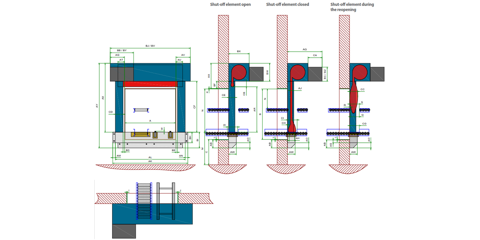
| A - Clear wall opening width | 500 mm to 6000 mm |
| B - Clear wall opening height | 500 mm to 4400 mm |
| C - Lower edge of wall opening | 0 - n |
| I - Planning allowance left | Default value 20 mm |
| J - Planning allowance right | Default value 20 mm |
| K - Planning surcharge above | Default value 20 mm |
| L - Planning surcharge below | Wall-hung system: default value = 20 mm Floor-standing system: default value = 0 mm |
| Q - Conveyor separation Width | Depending on the position and type of the conveyor system and the size of the clear wall opening dimensions |
| R - Conveyor separation dimension wall side | Depending on the position and type of the conveyor system and the size of the clear wall opening dimensions |
| S - Conveyor separation dimension room side | Depending on the position and type of the conveyor system and the size of the clear wall opening dimensions |
| N - Clearance height/headroom | Depending on the position and type of the conveyor system and the size of the clear wall opening dimensions |
| M - support level | 0 - n |
| W - conveying level protrusion | up to +25 mm |
| AA - Space requirement above the opening | BF + BW + K unseparated continuous conveying = 200 mm + 430 mm + 20 mm = 650 mm separated conveyor technique = 50 mm + 430 mm + 20 mm = 500 mm |
| AB - Space requirement below the opening | with fixed panel = L + AS + AO = 20 mm + 80 mm + 120 mm = 220 mm without fixed field = 0 mm |
| AG - Space requirement drive Installation side | 800 mm |
| AH - Sealing depth at the shut-off element | 150 mm |
| AI - Sealing depth at the fixed panel | 175 mm |
| AJ - Thickness barrier element | approx. 12 mm |
| AK - Total fixed field width | AL + AM + AN |
| AL - Fixed field width | A + I + J + CD + CD = A + 20 mm + 20 mm + 230 mm + 230 mm = A + 500 mm |
| AM - Fixing projection fixed panel left | 50 mm |
| AN - Fixing projection fixed panel right | 50 mm |
| AO - Fixing protrusion fixed panel below | 120 mm |
| AQ - Space requirement for wall frame to the left of the opening | I + BD + CD + 100 mm = 20 mm + 50 mm + 230 mm + 100 mm = 400 mm |
| AR - Traverse path of shut-off element / unwinding length | = N |
| AS - Overlap fixed field below | 80 mm |
| AT - Overlap fixed field left | 215 mm |
| AU - Overlap fixed field right | 215 mm |
| AV - Space requirement wall frame to the right of the opening | J + BE + CD + 100 mm = 20 mm + 50 mm + 230 mm + 100 mm = 400 mm |
| AW - Fixed field depth | 175 mm |
| AX - Height wall frame | N + AA unseparated continuous conveyor = N + 650 mm separated conveyor technique = N + 500 mm |
| AY - System height | BI + AX |
| BB - Drive Technology Width | 750 mm |
| BC - Drive Technology Height | 430 mm |
| BD - Offset left | 50 mm |
| BE - Offset right | 50 mm |
| BF - Offset top | unseparated continuous conveyor = 200 mm separated conveyor technology = 50 mm |
| BH - fixed field height | M - C + L + AS |
| BI - Total fixed field height | BH + AO |
| BJ - System width | AQ + AV + A = 400 mm + 400 mm + A |
| BV - Winding case width | = BJ |
| BW - Winding case height | 430 mm |
| BX - Winding case depth | 460 mm |
| BY - Drive housing width | 750 mm |
| BZ - Drive housing height | 430 mm |
| CA - Drive housing depth | 340 mm |
| CB - Parking area Shut-off element under winding housing | unseparated continuous conveyor = 200 mm separated conveyor technology = 0 mm |
| CC - Thickness barrier element on reopening | 400 mm |
| CD - Guide rail width | 230 mm |
| CE -Guide rail depth | 114 mm |
| CF - Guide rail height | AX - BW |
| CG - Separation point conveyor system guide width | 300 mm |
| CH - Separation point conveyor guide dimension wall side | 0 mm |
| CI - Separation point conveyor guide dimension room side | 300 mm |
| CJ - width/height ratio | BJ/CF >= 0.333 |