• NL
  • Oplossingen
    • Fire Protection Bonnets

      Fire Protection Bonnets

      • Copy-Cap WV
      • Copy-Cap WH
    • Fire protection curtains

      Fire protection curtains

      In case of fire, fire protection curtains close wall and ceiling openings. Their construction (roll-down or folding technique) and the use of different fabrics provide for a wide range of applications as well as different protection goals, classifications and time classes. The casing and guide rails of the highly flexible systems blend almost invisibly into the building and allow plenty of scope for sophisticated architecture and open room concepts.

      • Fibershield®-P
      • Fibershield®-E
      • Fibershield®-I
      • Fibershield®-HC
      • Fibershield®-S
      • Fibershield®-F
    • Conveyor system closures

      Conveyor system closures

      Various production and logistics processes call for the most diverse types of conveyor systems. If these conveyor lines pass through fire-retardant or fire-resistant walls or ceilings, the openings required for this purpose must be provided with fire protection closures to prevent the spread of fire through the conveyor system or the goods conveyed. In the event of fire, conveyor system closures (CSC for short) must close these openings immediately and automatically. Fire resistance classified according to DIN EN 13501-2 is just as important as the smooth clearance of the closing areas in the event of a fire.

      • ECClos®-S
      • ECClos®-Q
      • ECClos®-FLEX-I
      • Ecotube
      • GCC
      • BR100
    • Smoke curtains

      Smoke curtains

      A smoke apron is a part of a smoke control system which also includes other components such as natural smoke and heat exhaust ventilators (EN 12101-2) and mechanical smoke and heat exhaust ventilators (EN 12101-3). Smoke aprons restrict the movement of combustion gases within a building in case of fire.

      • Supercoil
      • Stripecoil
      • Smokeshield-S
      • Fixed smoke apron
    • Smoke protection curtains

      Smoke protection curtains

      Once closed, smoke protection curtains (SPC) restrict the passage of smoke during the phase of fire formation, so that in the event of a fire, there is enough time to rescue people and animals from the room behind the curtain and to recover material assets without the need for respiratory equipment.

      • Fiberseal
    • Gates

      Gates

      The solution for issues with fire protection dampers in ventilation and air conditioning systems in conveyor processes. Stöbich offers fire protection for pneumatic conveyor lines the closing elements of which are not exposed to the flow of conveyed material. This way, the closing element cannot be damaged or contaminated by abrasive conveyed goods.

      • Omnicompact
    • Control units

      Control units

      Each automatic fire protection system needs a control unit. They are critical to safety, because a failure of this function means that the entire investment into a fire protection sealing has been in vain. Control units coordinate both fire detection and interaction with other control units, such as higher-level building control systems or clearing of the closing area of conveyor system closures.

      • RZ7
      • RZ3/4
      • RZ8
      • Battery system
      • Movipower 350/550
      • UPS
      • FFE-KDR
    • Special Solutions
      • ECClos®-D
      • ECClos®-K
      • Universal-B
      • Universal-S
      • ECClos®-FLEX
      • Collar
      • Turbocoil
      • Omnitube
    • Technical Fire Protection
      • Fire Multi Detektor
    • Fire protection for battery storage
      • Strainbox XS
      • Strainbox S
      • Strainbox L
      • Strainbox XL
      • Strainlock
      • Packaging Cushions
    • Service
  • Referenties
  • Over Stöbich
  • Wereldmarktleider
  • Duurzaamheid
  • Actueel
  • Contact

SYSTEEM: FIBERSHIELD® | SERIE: FIBERSEAL

  • Fiberseal

Productbeschrijving

In het geval van een alarm zelfsluitende, niet warmte-isolerende brand- en rookafsluiting textiel-constructie in verticale inbouwpositie en sluitrichting.

FunctieRookwerende afsluiting van textielconstructie of niet-warmte-isolerend brand- en rookwerend gordijn
BewijsCE-markering volgens EN 16034:2014 in combinatie met EN 13241:2003+A2:2016
Sluitrichtingvan boven naar beneden
BrandwerendheidE 0 – EW 120 | getest volgens EN 1634-1:2014+A1:2018 | geclassificeerd volgens EN 13501-2:2016
RookbeveiligingSa, S200 | getest volgens EN 1634-3:2005-01 | geclassificeerd volgens EN 13501-2:2016
SluitingscycliC, C1, C2 | getest volgens EN 12605:2000-08 en EN 12604:2017-12 | geclassificeerd volgens EN 13501-2:2016
Brandgedrag van het branddoekA2-s1, d0; B-s1, d0; E-d2 | getest volgens ISO 1716 en EN 13823 resp. ISO 11295-2 | geclassificeerd volgens EN 13501-1:2018
MilieuconditiesEr wordt geen rekening gehouden met bijzondere omgevingsomstandigheden (bv. vochtigheid > 80%, omgevingstemperatuur < 5°C en > 45°C, windbelasting, enz.
Zichtbare oppervlakkengegalvaniseerd, RAL - glad - zijdeglans - standaardkleur, NCS - standaardkleur
Fiberseal

Delen van het systeem:
1 = Rookmelder
2 = Behuizing
3 = Geleiderail
4 = Bedieningsmodule
5 = Apparaat vrijgeven (Details over de elektrische componenten zijn te vinden in de geldige algemene typegoedkeuring van het vastzetsysteem.)

Wettelijke afmetingen:
Lichaam
B = Vrije onafgewerkte hoogte
A = Vrije onafgewerkte breedte
systeem
AY = Systeemhoogte
LH = Systeemhoogte vrijmaken
LB = Systeembreedte vrijmaken
BJ = Systeembreedte
Behuizing
BX = Diepte
BW = Hoogte
v = Offset tussen geleiderail en behuizing
Geleidingsrail
CD = Breedte
CE = Diepte
BD = Offset links
BE = Offset rechts

Constructief systeemontwerp (systeemtekening)

Door de combinatie van classificaties of de verhouding van lichte systeembreedte ten opzichte van lichter systeemhoogte kunt u de genoemde maximale afmetingen reduceren. De specificaties op de offerte zijn geldig.

Classificatie BrandveiligheidMaat max* [y x r] in mmWeefselWanddikte** in mmBehuizingGeleiderails
E 30, EW 307700 x 5000Heliotex 9150Typ A, B, C, D, ETyp 1, 2
E 60, EW 607700 x 5000Heliotex 9150Typ A, B, C, D, ETyp 1, 2
E 90, EW 907700 x 5000Heliotex 9150Typ A, B, C, D, ETyp 1, 2
E1207700 x 5000Heliotex 9175Typ A, B, C, D, ETyp 1, 2
E120, EW 1204340 x 2700Heliotex 9175Typ A, B, C, D, ETyp 1, 2
C0, C17500 x 5000Protex 600 2S
C0, C1, C27002 x 4500Protex 1100 2S
C0, C1, C27500 x 5000Heliotex 9
Sa ***Voeglengte van 14,85 mProtex 600 2STyp A, B, C, D, E
Sa ***Voeglengte van 14,85 mProtex 1100 2STyp A, B, C, D, E
Sa ***Voeglengte van 14,85 mHeliotex 9Typ A, B, C, D, E
S200 ****Afmeting 25,2 m2
Joint lengte van 20,1 m
Protex 600 2S
Protex 1100 2S
Heliotex 9

De installatiesituatie moet voldoen aan de bouwvoorschriften van het land van installatie. De brandwerendheid van een plafond- of wanddraagconstructie en de aangrenzende onderdelen moet ten minste overeenkomen met die van de brand- en/of rookwerende afsluiting of die van het brand- en/of rookwerende gordijn. De stabiliteit en geschiktheid voor gebruik van de aangrenzende wanden en wanden en componenten moet worden gegarandeerd onder algemene omgevingsomstandigheden en in geval van brand. Zie ook de opmerkingen over de gestandaardiseerde draagconstructie in EN1366-7:2004 en EN1363-1:2020. Het brandbeveiligingssysteem mag niet worden blootgesteld aan enige andere extra belasting dan zijn eigen gewicht, zelfs niet in geval van brand.
* Afwijkingen van maatafmetingen op aanvraag
** geteste wandtypes volgens de installatievoorschriften
*** normatief: 3-zijdig zonder eindlijst mag niet overschreden worden!
**** normatief: 4-zijdig mag niet overschreden worden!
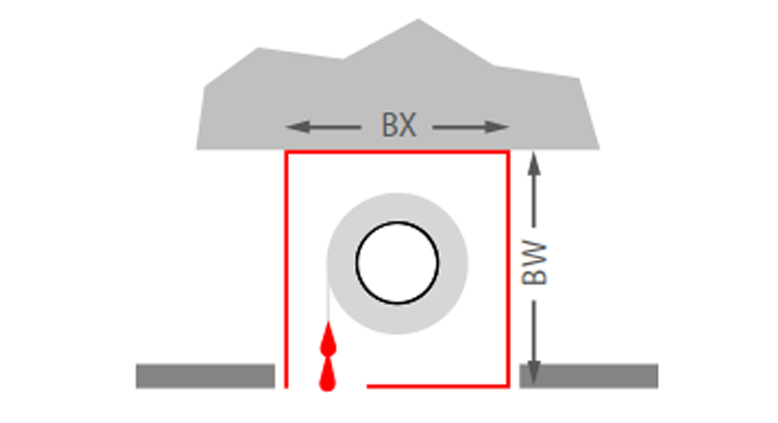
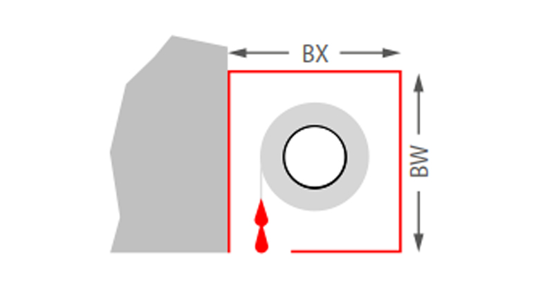
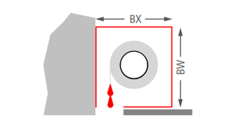
Behuizing


Fiberseal
Plafondmontage
Typ A: BX = 285 mm, BW = 200 mm
Typ B: BX = 350 mm, BW = 260 mm
Typ C: BX = 190 mm, BW = 290 mm
Typ D: BX = 290 mm, BW = 360 mm
Typ E: BX = 380 mm, BW = 420 mm
Fiberseal
Wandmontage
Typ B: BX = 350 mm, BW = 260 mm
Typ C: BX = 190 mm, BW = 290 mm
Typ D: BX = 290 mm, BW = 360 mm
Typ E: BX = 380 mm, BW = 420 mm
Fiberseal
Wandmontage verlaagd plafond met kap
Typ B: BX = 350 mm, BW = 260 mm
Typ C: BX = 190 mm, BW = 290 mm
Typ D: BX = 290 mm, BW = 360 mm
Typ E: BX = 380 mm, BW = 420 mm

Geleiderails


Typ 1
Typ 1 (Wandmontage>)
CD = 104 mm
CE = 74 mm
BD/BE ≥ 0 mm
v = 0 mm
Typ 2
Typ 2 (Kozijnmontage)
CD = 104 mm
CE = 74 mm
v = 0 mm
Typ 2
Typ 2 (Nismontage)
CD = 104 mm
CE = 74 mm
v = 0 mm

CDN = 120 mm
CEN = 100 mm

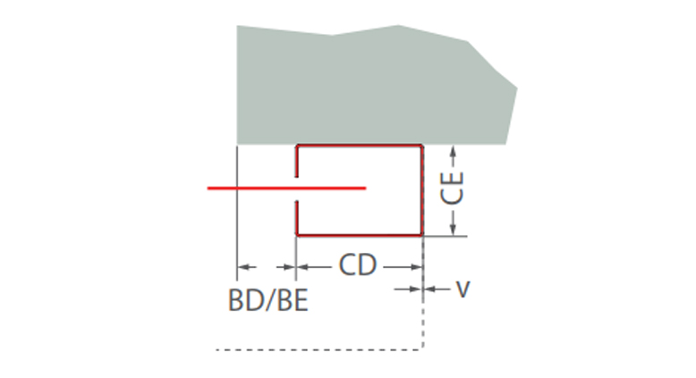
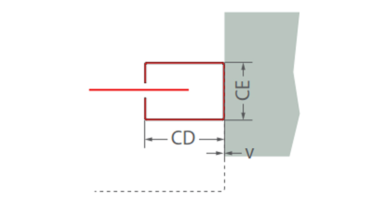
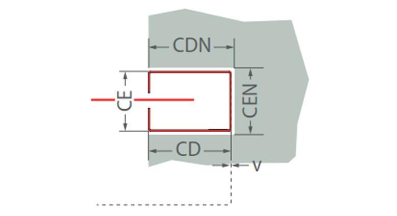
Opmerking: Stippellijn voor wikkelassteun (behuizing)