SYSTEM: FIBERSHIELD® | MODEL: FIBERSEAL

| Function | Smoke protection closure of textile construction or non-thermally insulating fire and smoke protection closure |
| Verification | CE identification pursuant to EN 16034:2014 in conjunction with EN 13241:2003+A2:2016 |
| Closing direction | From top to bottom |
| Fire resistance | E 0 – EW 120 | tested in compliance with EN 1634-1:2014+A1:2018 | Classified according to EN 13501-2:2016 |
| Smoke protection | Sa, S200 | tested in compliance with EN 1634-3:2005-01 | classified according to EN 13501-2:2016 |
| Closing cycles | C, C1, C2 | tested in compliance with EN 12605:2000-08 and EN 12604:2017-12 | classified according to EN 13501-2:2016 |
| Fire behaviour of the fabric | A2-s1, d0; B-s1, d0; E-d2 | tested in compliance with ISO 1716 and EN 13823 or ISO 11295-2 | classified according to EN 13501-1:2018 |
| Environment conditions | Special environmental conditions are not taken into account (e.g. humidity > 80 %, ambient temperature < 5 °C and > 45 °C, wind loads etc.) |
| Visible surfaces | galvanized, RAL - smooth - silk gloss - standard shade, NCS - standard shade |

Structural system design (system drawing)
The combination of classifications or the ratio of clear system width to clear system height may reduce the stated maximum dimensions and the dimensions of the housing and guide rails may vary. The specifications on the quotation apply.
| Classification | Size max* [y x r] in mm | Fabric | Wall thickness** in mm | Housing | Guide rail |
| E 30, EW 30 | 7700 x 5000 | Heliotex 9 | 150 | Type A, B, C, D, E | Type 1, 2 |
| E 60, EW 60 | 7700 x 5000 | Heliotex 9 | 150 | Type A, B, C, D, E | Type 1, 2 |
| E 90, EW 90 | 7700 x 5000 | Heliotex 9 | 150 | Type A, B, C, D, E | Type 1, 2 |
| E120 | 7700 x 5000 | Heliotex 9 | 175 | Type A, B, C, D, E | Type 1, 2 |
| E120, EW 120 | 4340 x 2700 | Heliotex 9 | 175 | Type A, B, C, D, E | Type 1, 2 |
| C0, C1 | 7500 x 5000 | Protex 600 2S | |||
| C0, C1, C2 | 7002 x 4500 | Protex 1100 2S | |||
| C0, C1, C2 | 7500 x 5000 | Heliotex 9 | |||
| Sa *** | Joint length of 14.85 m | Protex 600 2S | Type A, B, C, D, E | ||
| Sa *** | Joint length of 14.85 m | Protex 1100 2S | Type A, B, C, D, E | ||
| Sa *** | Joint length of 14.85 m | Heliotex 9 | Type A, B, C, D, E | ||
| S200 **** | Surface 25.2 m2 Joint length of 20.1 m | Protex 600 2S Protex 1100 2S Heliotex 9 |
The installation situation must comply with the building regulations of the country of installation. The fire resistance of a ceiling or wall supporting structure and the adjoining components must correspond at least to that of the fire and / or smoke protection closure or that of the fire and / or smoke protection curtain. Proof of the stability and suitability for use of the adjacent walls and walls and components must be ensured under general ambient conditions and in the event of fire. See also notes on the standard supporting structure in EN1366-7:2004 and EN1363-1:2020. fire protection system must not be subjected to any additional load other than its own weight, even in the event of a fire
* Deviations from size dimensions on request
** tested wall types according to the installation instructions
*** normative: 3-sided without termination strip must not be exceeded!
**** normative: 4-sided must not be exceeded!
Housing
Guide rails
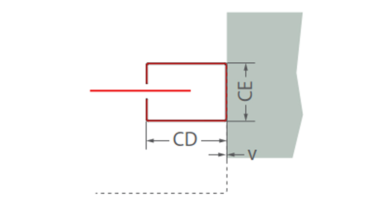
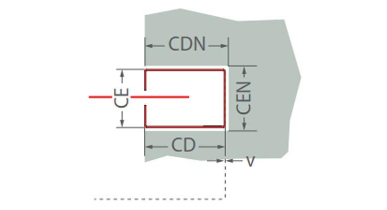
Note: Dotted line for the winding shaft receptacle (housing)