• EN
  • Solutions
    • Fire protection curtains

      Fire protection curtains

      Fire protection curtains are seal openings in walls and ceilings in case of fire. The constructional set-up (rolling- or folding technology) and the use of different fabrics offer a wide application spectrum as well as different protection targets or classifications and time classes. Casings and side guides of those flexible applicable systems are integrated almost invisibly in the building and provide much scope for design of sophisticated architecture for opened designs.

    • Conveyor system closures

      Conveyor system closures

      Manifold production - and logisitc processes require different construction types of conveying systems. If the haulage drifts are passing through fire-retarding resp. fire-resisting walls or ceilings, the necessary openings must be provided with fire protection closures to avoid the expansion of the fire by conveyor technique or by conveyed material. In case of fire the conveyor system closures have to seal those openings immediately and automatically. Thereby a classified fire resistance as well as the smoothly clearing of the closing area must be respected in case of release.

    • Smoke curtains

      Smoke curtains

      A smoke curtain is part of unit keeping areas free from smoke and may include building parts like natural smoke and heat venting systems and automatic smoke and heat venting systems. Smoke curtains restrict the movement of fire gases inside a building in case of fire.

    • Smoke protection closures

      Smoke protection closures

      In closed condition smoke protection closures restrict the passage of smoke in the phase of fire formation so as to enable the rescue of people, animals or materials assets in case of a fire in the room positioned behind it without the need of breathing protection.

    • Tube sealings

      Tube sealings

      The solution to problems with fire protection dampers for ventilation and air conditioning systems in conveying processes. Stöbich offers fire protection for pneumatic conveying lines where the closing elements are not exposed to the flow. Thus, damage or contamination of the closure element is avoided by abrasive conveyed goods.

    • Controls

      Controls

      Control systems are necessary for all automatic fire protection systems! They are safety-relevant, because without their function or in the event of a malfunction, the entire investment of a fire protection partition would be useless. Controllers coordinate both fire detection and the interaction with other controls, like superordinate building control or the retraction of the closing area at conveyor closing area.

    • Médiathèque Charles Nègre | Grasse, France

      Médiathèque Charles Nègre | Grasse, France

      The Médiathèque Charles Nègre in Grasse, France, is an impressive example of contemporary architecture that reflects the cultural and historical importance of the region. The information center with space for education, culture and encounters was opened in 2011 and designed by the renowned French architecture firm Marc Barani. The building combines modern aesthetics with the traditional architecture of Provence, creating a harmonious link between old and new, for example by combining modern materials such as glass and steel with local natural stone. The generous window fronts create an atmosphere flooded with light. Ecological sustainability is achieved through natural ventilation and the resulting reduction in energy consumption; green spaces are also integrated on various levels. Our <a href="/us/solutions/fire-protection-curtains/stoebich-fire-smoke-curtain-hc"><b>➥ horizontal Fire and smoke curtain hc</b></a> fire protection curtains fit perfectly into this marvel of contemporary architecture. They securely close the ceiling openings in the event of a fire, but otherwise remain invisible and let in plenty of light and air. Copyright attribution: © Ivry Serres

  • References
  • Theme worlds
  • World market leader
  • Sustainability
  • News
  • Contact

SYSTEM: FIBERSHIELD® | SERIES FIBERSHIELD®-P

  • Fibershield-P

Product description

In the event of an alarm, self-closing, non-thermally insulating fire protection curtain in vertical installation position and closing direction with architectural requirements for housing and guide rails.

Type of constructionNon-thermally insulating fire curtain
ProofCE labelling in accordance with EN 16034:2014 in conjunction with EN 13241:2003+A2:2016
Closing directionfrom top to bottom
Fire resistance E 30 - E 120 | EW 30 - EW 120 | tested according to EN 1634-1:2014+A1:2018 | classified according to EN 13501-2:2016
Closing cyclesC0, C, C1, C2 | tested according to EN 12605:2000-08 and EN 12604:2017-12 | classified according to EN 13501-2:2016
Fire behaviour of the textileA2-s1, d0; B-s1, d0; E-d2 | tested according to ISO 1716 and EN 13823 or ISO 11295-2 | classified according to EN 13501-1:2018
Environmental conditionsNot taken into account are special environmental conditions (e.g. humidity > 80 %, ambient temperature < 5 °C and > 40 °C, wind loads, etc.)
Visible surfaces galvanised | RAL, smooth, semi-gloss, standard colour shade | NCS, standard colour shade
Fibershield-P

Key: System components:
1 = Smoke detector
2 = Housing
3 = Guide rail
4 = Control module
5 = Release device (see the valid general type approval of the brake system for design details of the electrical components.)

Key: Dimensions
Structure
B = Clear shell construction height
A = Clear shell construction width
System
AY = System height
LH = Clear system height
LB = Clear system width
BJ = System width
Housing
BX = Depth
BW = Height
v = Offset between housing and guide rail
Guide rail
CD = Width
CE = Depth
BD = Offset left
BE = Offset right

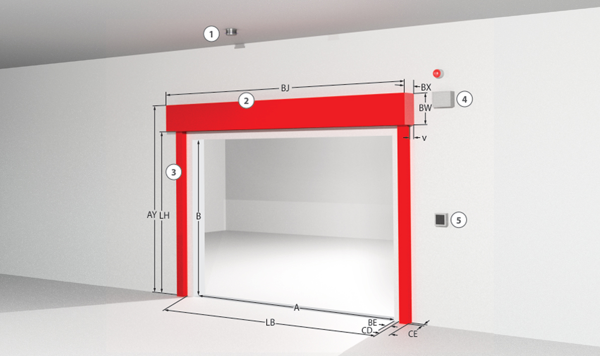
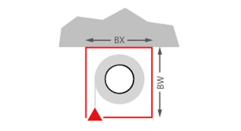
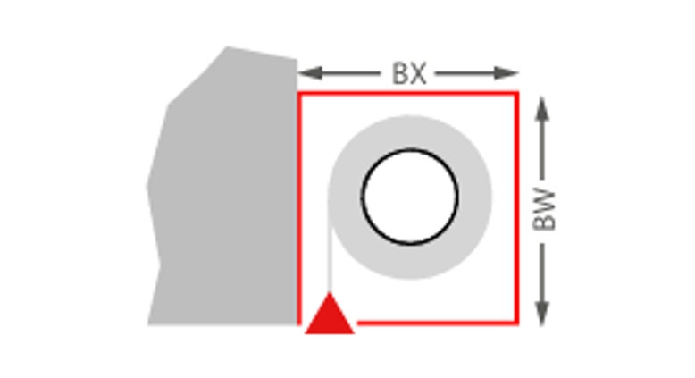
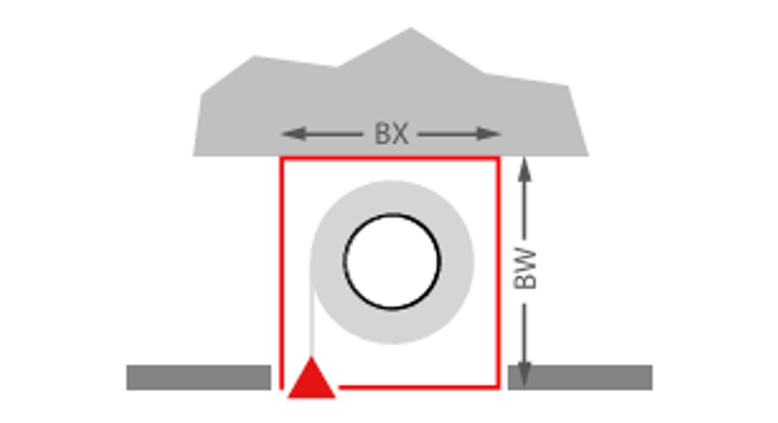
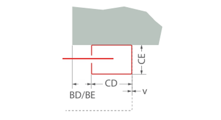
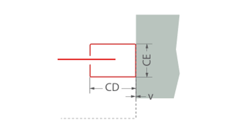
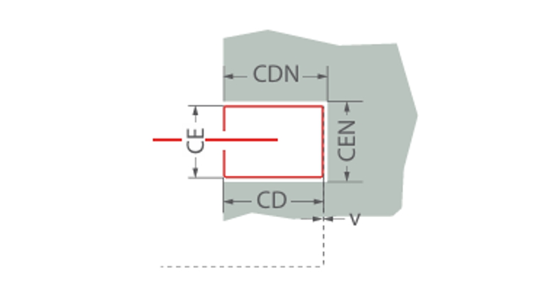
Size dimensions and system structure

Classification Fibershield®-P series

Fire resistance class/
Classifications
Size* [LW x LH] in mmFabricWall thickness** in mmWrapped housingGuide rails
E 3011000 x 8000Protex 1100 1.A2140Typ A, B, CTyp 1, 2, 3
E 6011000 x 8000Protex 1100 1.A2140Typ A, B, CTyp 1, 2, 3
E 9011000 x 8000Protex 1100 1.A2200Typ A, B, CTyp 1, 2, 3
E 12011000 x 8000Protex 1100 1.A2200Typ A, B, CTyp 1, 2, 3
EW 3011000 x 8000Protex 1100 1.A2140Typ A, B, CTyp 1, 2, 3
EW 3012000 x 7500Heliotex 9140Typ B, C, D, ETyp 1, 2, 3
EW 6012000 x 7500Heliotex 9200Typ B, C, D, ETyp 1, 2, 3
EW 9012000 x 7500Heliotex 9200Typ B, C, D, ETyp 1, 2, 3
EW 12011000 x 3300Heliotex 12200Typ B, C, D, ETyp 1, 2, 3
E 12012000 x 7500Heliotex 9200Typ B, C, D, ETyp 1, 2, 3
C0, C111000 x 4200Heliotex 9
C0, C1, C27500 x 5000Heliotex 9
C0, C1, C211000 x 9800Protex 1100 1.A2

The installation situation must comply with the building regulations of the country of installation. The fire resistance of a ceiling or wall supporting structure and the neighbouring components must at least correspond to that of the fire and/or smoke protection closure/fire and/or smoke protection curtain. Proof of the stability and serviceability of the neighbouring walls and components must be provided under general ambient conditions and in the event of fire. See also notes on the standard load-bearing structure in EN1366-7:2004 or EN1363-1:2020. The fire protection system must not be subjected to any additional load other than its own weight, even in the event of fire.
* Deviations from size dimensions on request
** Tested wall types according to the installation instructions

Winding housing


Ceiling mounting
Ceiling mounting
Typ A: BX = 190 mm, BW = 200 mm
Typ B: BX = 190 mm, BW = 250 mm
Typ C: BX = 235 mm, BW = 295 mm
Typ D: BX = 270 mm, BW = 320 mm
Typ E: BX = 300 mm, BW = 340 mm
Wall mounting
Wall mounting
Typ A: BX = 190 mm, BW = 200 mm
Typ B: BX = 190 mm, BW = 250 mm
Typ C: BX = 235 mm, BW = 295 mm
Typ D: BX = 270 mm, BW = 320 mm
Typ E: BX = 300 mm, BW = 340 mm
Ceiling installation suspended ceiling
Typ A: BX = 190 mm, BW = 200 mm
Typ B: BX = 190 mm, BW = 250 mm
Typ C: BX = 235 mm, BW = 295 mm
Typ D: BX = 270 mm, BW = 320 mm
Typ E: BX = 300 mm, BW = 340 mm

Guide rails


Wall mounting
Wall mounting
Typ 1: CD = 80 mm | CE = 74 mm
Typ 2: CD = 105 mm | CE = 74 mm
Typ 3: CD = 160 mm | CE = 100 mm

BD/BE ≥ 0 mm
v = 0 mm
Soffit mounting
Soffit mounting
Typ 1: CD = 80 mm | CE = 74 mm
Typ 2: CD = 105 mm | CE = 74 mm
Typ 3: CD = 160 mm | CE = 100 mm

v = 0 mm
Recess mounting
Recess mounting
Typ 1: CD = 80 mm | CE = 74 mm
Typ 2: CD = 105 mm | CE = 74 mm
Typ 3: CD = 160 mm | CE = 100 mm

CDN = + 15 mm
CEN = + 15 mm