• NL
  • Oplossingen
    • Fire Protection Bonnets

      Fire Protection Bonnets

      • Copy-Cap WV
      • Copy-Cap WH
    • Fire protection curtains

      Fire protection curtains

      In case of fire, fire protection curtains close wall and ceiling openings. Their construction (roll-down or folding technique) and the use of different fabrics provide for a wide range of applications as well as different protection goals, classifications and time classes. The casing and guide rails of the highly flexible systems blend almost invisibly into the building and allow plenty of scope for sophisticated architecture and open room concepts.

      • Fibershield®-P
      • Fibershield®-E
      • Fibershield®-I
      • Fibershield®-HC
      • Fibershield®-S
      • Fibershield®-F
    • Conveyor system closures

      Conveyor system closures

      Various production and logistics processes call for the most diverse types of conveyor systems. If these conveyor lines pass through fire-retardant or fire-resistant walls or ceilings, the openings required for this purpose must be provided with fire protection closures to prevent the spread of fire through the conveyor system or the goods conveyed. In the event of fire, conveyor system closures (CSC for short) must close these openings immediately and automatically. Fire resistance classified according to DIN EN 13501-2 is just as important as the smooth clearance of the closing areas in the event of a fire.

      • ECClos®-S
      • ECClos®-Q
      • ECClos®-FLEX-I
      • Ecotube
      • GCC
      • BR100
    • Smoke curtains

      Smoke curtains

      A smoke apron is a part of a smoke control system which also includes other components such as natural smoke and heat exhaust ventilators (EN 12101-2) and mechanical smoke and heat exhaust ventilators (EN 12101-3). Smoke aprons restrict the movement of combustion gases within a building in case of fire.

      • Supercoil
      • Stripecoil
      • Smokeshield-S
      • Fixed smoke apron
    • Smoke protection curtains

      Smoke protection curtains

      Once closed, smoke protection curtains (SPC) restrict the passage of smoke during the phase of fire formation, so that in the event of a fire, there is enough time to rescue people and animals from the room behind the curtain and to recover material assets without the need for respiratory equipment.

      • Fiberseal
    • Gates

      Gates

      The solution for issues with fire protection dampers in ventilation and air conditioning systems in conveyor processes. Stöbich offers fire protection for pneumatic conveyor lines the closing elements of which are not exposed to the flow of conveyed material. This way, the closing element cannot be damaged or contaminated by abrasive conveyed goods.

      • Omnicompact
    • Control units

      Control units

      Each automatic fire protection system needs a control unit. They are critical to safety, because a failure of this function means that the entire investment into a fire protection sealing has been in vain. Control units coordinate both fire detection and interaction with other control units, such as higher-level building control systems or clearing of the closing area of conveyor system closures.

      • RZ7
      • RZ3/4
      • RZ8
      • Battery system
      • Movipower 350/550
      • UPS
      • FFE-KDR
    • Special Solutions
      • ECClos®-D
      • ECClos®-K
      • Universal-B
      • Universal-S
      • ECClos®-FLEX
      • Collar
      • Turbocoil
      • Omnitube
    • Technical Fire Protection
      • Fire Multi Detektor
    • Fire protection for battery storage
      • Strainbox XS
      • Strainbox S
      • Strainbox L
      • Strainbox XL
      • Strainlock
      • Packaging Cushions
    • Service
  • Referenties
  • Over Stöbich
  • Wereldmarktleider
  • Duurzaamheid
  • Actueel
  • Contact

SYSTEEM: FIBERSHIELD® | SERIE FIBERSHIELD®-P

  • Fibershield-P

Productbeschrijving

In geval van alarm, zelfsluitend, niet-thermisch isolerend brandwerend gordijn in verticale installatiepositie en sluitrichting met architecturale vereisten voor behuizing en geleiderails.

Type constructieNiet-thermisch isolerend brandgordijn
BewijsCE-etikettering in overeenstemming met EN 16034:2014 in combinatie met EN 13241:2003+A2:2016
Sluitrichtingvan boven naar beneden
Brandwerendheid E 30 - E 120 | EW 30 - EW 120 | getest volgens EN 1634-1:2014+A1:2018 | geclassificeerd volgens EN 13501-2:2016
SluitcycliC0, C, C1, C2 | getest volgens EN 12605:2000-08 en EN 12604:2017-12 | geclassificeerd volgens EN 13501-2:2016
Brandgedrag van het textielA2-s1, d0; B-s1, d0; E-d2 | getest volgens ISO 1716 en EN 13823 of ISO 11295-2 | geclassificeerd volgens EN 13501-1:2018
MilieuomstandighedenEr wordt geen rekening gehouden met speciale omgevingsomstandigheden (bijv. luchtvochtigheid > 80%, omgevingstemperatuur < 5 °C en > 40 °C, windbelasting, enz.)
Zichtbare oppervlakken gegalvaniseerd | RAL, glad, halfglans, standaard kleurtint | NCS, standaard kleurtint
Fibershield-P

Legendarische systeemcomponenten:
1 = Rookmelder
2 = Huisvesting
3 = Geleiderail
4 = Stuurmodule
5 = Ontgrendelinrichting (Details van de elektrische onderdelen zijn te vinden in de geldige algemene typegoedkeuring van het vastzetsysteem.)

Wettelijke dimensionering:
Lichaam
B = wis onvoltooide hoogte
A = wis onafgewerkte breedte
systeem
AY = systeemhoogte
LH = clear system height
LB = duidelijke systeembreedte
BJ = systeembreedte
huisvesting
BX = diepte
BW = hoogte
v = Verschuiving tussen geleiderail en behuizing
Gidsrail
CD = breedte
CE = diepte
BD = offset links
BE = offset rechts

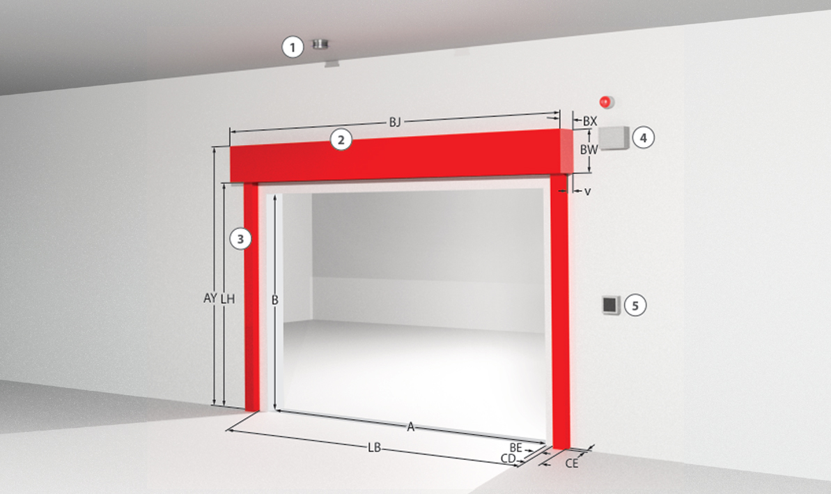
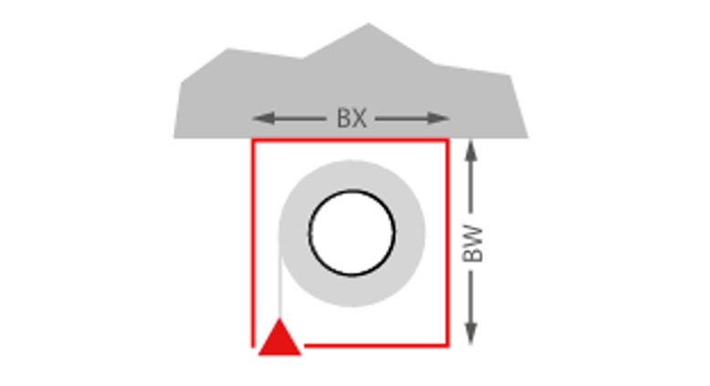
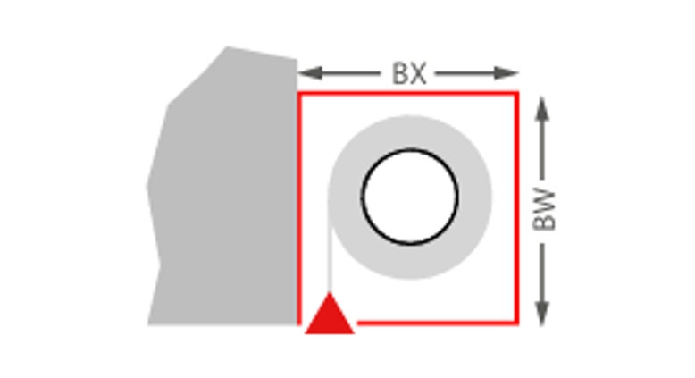
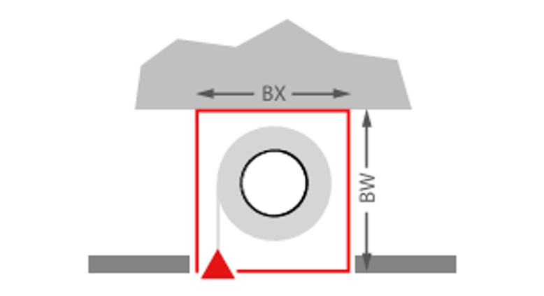
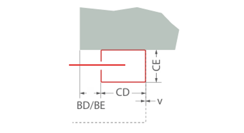
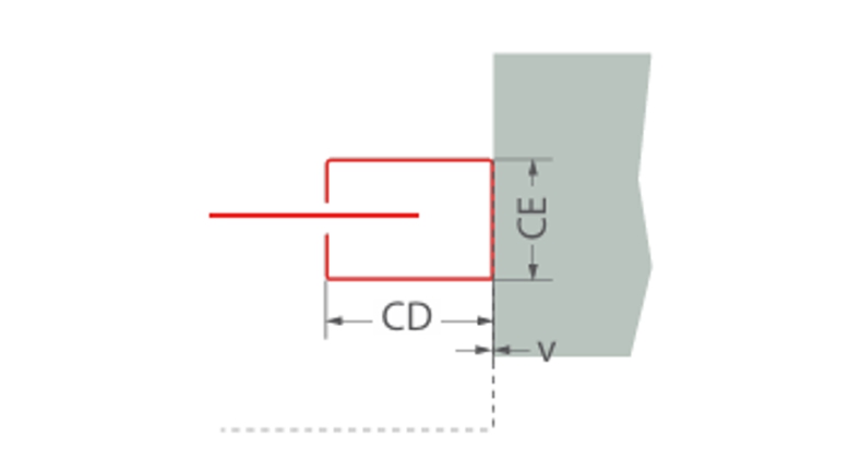
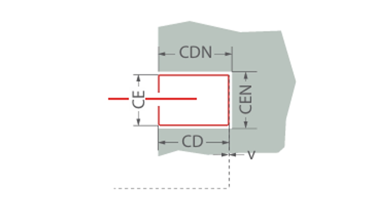
Afmetingen en systeemstructuur

Klassificatie Fibershield®-P serie

Brandwerendheidsklasse/
Classificaties
Afmeting* [LW x LH] in mmStofMuurdikte** in mmGewikkelde behuizingGeleiderails
E 3011000 x 8000Protex 1100 1.A2140Typ A, B, CTyp 1, 2, 3
E 6011000 x 8000Protex 1100 1.A2140Typ A, B, CTyp 1, 2, 3
E 9011000 x 8000Protex 1100 1.A2200Typ A, B, CTyp 1, 2, 3
E 12010000 x 8000Protex 1100 1.A2200Typ A, B, CTyp 1, 2, 3
EW 3010000 x 8000Protex 1100 1.A2140Typ A, B, CTyp 1, 2, 3
EW 3012000 x 7500Heliotex 9140Typ B, C, D, ETyp 1, 2, 3
EW 6012000 x 7500Heliotex 9200Typ B, C, D, ETyp 1, 2, 3
EW 9012000 x 7500Heliotex 9200Typ B, C, D, ETyp 1, 2, 3
EW 12011000 x 3300Heliotex 12200Typ B, C, D, ETyp 1, 2, 3
E 12012000 x 7500Heliotex 9200Typ B, C, D, ETyp 1, 2, 3
C0, C111000 x 4200Heliotex 9
C0, C1, C27500 x 5000Heliotex 9
C0, C1, C211000 x 9800Protex 1100 1.A2

De inbouwsituatie moet voldoen aan de bouwvoorschriften van het land van installatie. De brandwerendheid van een plafond- of wanddraagconstructie en de aangrenzende onderdelen moet ten minste overeenkomen met die van de brand- en/of rookwerende afsluiting/brand- en/of rookwerend gordijn. De stabiliteit en bruikbaarheid van de aangrenzende wanden en onderdelen moet worden aangetoond onder algemene omgevingsomstandigheden en in geval van brand. Zie ook de opmerkingen over de standaard draagconstructie in EN1366-7:2004 of EN1363-1:2020. Het brandbeveiligingssysteem mag geen andere extra belasting ondervinden dan zijn eigen gewicht, zelfs niet in geval van brand.
* Afwijkingen van maatafmetingen op aanvraag
** Geteste wandtypes volgens de installatievoorschriften

Wikkelhuis


Plafondmontage
Plafondmontage
Typ A: BX = 190 mm, BW = 200 mm
Typ B: BX = 190 mm, BW = 250 mm
Typ C: BX = 235 mm, BW = 295 mm
Typ D: BX = 270 mm, BW = 320 mm
Typ E: BX = 300 mm, BW = 340 mm
Wandmontage
Wandmontage
Typ A: BX = 190 mm, BW = 200 mm
Typ B: BX = 190 mm, BW = 250 mm
Typ C: BX = 235 mm, BW = 295 mm
Typ D: BX = 270 mm, BW = 320 mm
Typ E: BX = 300 mm, BW = 340 mm
Plafondinstallatie verlaagd plafond
Typ A: BX = 190 mm, BW = 200 mm
Typ B: BX = 190 mm, BW = 250 mm
Typ C: BX = 235 mm, BW = 295 mm
Typ D: BX = 270 mm, BW = 320 mm
Typ E: BX = 300 mm, BW = 340 mm

Geleiderails


Wandmontage
Wandmontage
Typ 1: CD = 80 mm | CE = 74 mm
Typ 2: CD = 105 mm | CE = 74 mm
Typ 3: CD = 160 mm | CE = 100 mm

BD/BE ≥ 0 mm
v = 0 mm
Montage op dakgoot
Montage op dakgoot
Typ 1: CD = 80 mm | CE = 74 mm
Typ 2: CD = 105 mm | CE = 74 mm
Typ 3: CD = 160 mm | CE = 100 mm

v = 0 mm
Verzonken montage
Verzonken montage
Typ 1: CD = 80 mm | CE = 74 mm
Typ 2: CD = 105 mm | CE = 74 mm
Typ 3: CD = 160 mm | CE = 100 mm

CDN = + 15 mm
CEN = + 15 mm