• DE
  • World market leader
  • Sustainability
  • Solutions
    • Feuerschutzvorhänge

      Feuerschutzvorhänge

      Feuerschutzvorhänge dienen im Brandfall dem Verschluss von Wand- oder Deckenöffnungen. Ihr konstruktiver Aufbau (Abroll- oder Falttechnik) und der Einsatz verschiedener Gewebe ermöglichen ein breites Anwendungsspektrum sowie unterschiedliche Schutzziele oder Klassifizierungen und Zeitklassen. Gehäuse und Führungsschienen der flexibel einsetzbaren Systeme fügen sich nahezu unsichtbar in das Bauwerk und bieten viel Gestaltungsfreiraum für anspruchsvolle Architektur offener Raumkonzepte.

    • Förderanlagenabschlüsse

      Förderanlagenabschlüsse

      Vielfältige Produktions- und Logistikprozesse erfordern unterschiedlichste Bauarten von Förderanlagen. Wenn diese Förderstrecken durch feuerhemmende bzw. feuerbeständige Wände oder Decken führen, müssen die hierfür notwendigen Öffnungen mit Feuerschutzabschlüssen versehen werden, um eine Ausbreitung des Feuers über die Fördertechnik oder das Fördergut zu verhindern. Im Brandfall müssen Förderanlagenabschlüsse (kurz FAA) diese Öffnungen unverzüglich und automatisch verschließen. Dabei kommt es auf einen nach DIN EN 13501-2 klassifizierten Feuerwiderstand ebenso an, wie auf das reibungslose Freiräumen der Schließbereiche im Auslösungsfall.

    • Rauchschürzen

      Rauchschürzen

      Eine Rauchschürze ist ein Teil einer Anlage zur Rauchfreihaltung, welches auch andere Bauteile wie natürliche Rauch- und Wärmeabzugsgeräte (EN 12101-2) und maschinelle Rauch- und Wärmeabzugsgeräte (EN 12101-3) beinhaltet. Rauchschürzen schränken dabei die Bewegung von Brandgasen innerhalb eines Bauwerks im Falle eines Brandes ein.

    • Rauchschutzvorhänge

      Rauchschutzvorhänge

      Rauchschutzvorhänge (RSV) behindern im geschlossenen Zustand den Durchtritt von Rauch in der Brandentstehungsphase, so dass während eines Brandfalls im dahinter liegenden Raum für die Rettung von Menschen und Tieren sowie für die Bergung von Sachwerten auch ohne Atemschutz ausreichend Zeit verbleibt.

    • Tore

      Tore

      Die Lösung für Probleme bei Brandschutzklappen für raumlufttechnische Anlagen in Förderprozessen. Stöbich bietet Brandschutz für pneumatische Förderleitungen, bei denen die Verschlusselemente nicht dem Förderstrom ausgesetzt sind. So wird eine Beschädigung oder Verschmutzung des Verschlusselements durch abbrasive Fördergüter vermieden.

    • Steuerungen

      Steuerungen

      Steuerungen sind für alle automatischen Brandschutzsysteme notwendig! Sie sind sicherheitsrelevant, denn ohne deren Funktion oder bei Fehlfunktion würde die gesamte Investition einer Brandschutzabschottung null und nichtig sein. Steuerungen koordinieren sowohl Branderkennung als auch das Zusammenspiel mit anderen Steuerungen, wie z. B. übergeordnete Gebäudeleittechnik oder das Freifahren des Schließbereiches bei Förderanlagenabschlüssen.

    • Brandschutzhauben für Elektronikgeräte

      Brandschutzhauben für Elektronikgeräte

      Steht Ihr Kopierer oder Drucker auch im Gang, damit ein Zugang von allen Seiten möglich ist? Haben Sie durch diesen Standort des Kopierers auch einen optimalen Betriebsablauf geschaffen? Wussten Sie, dass Sie Leben dadurch gefährden? Kopierer haben ein großes Brandentstehungsrisiko durch die Beheizung der Fixiereinheit. Ein Versagen des Thermoschalters führt zur Überhitzung und dann zum Entstehungsbrand.

    • Sonderlösungen
  • References
  • Theme worlds
  • Contact

SYSTEM: FIBERSHIELD® MODEL: FIBERSHIELD®-E

Fibershield-E

Product description

In the event of an alarm, self-closing non-thermally insulating fire curtain in vertical installation position and closing direction with small winding housing and guide rails.

TypeNon-insulating fire curtain
VerificationCE marking according to EN 16034:2014 in conjunction with EN 13241:2003+A2:2016
Closing directionFrom top to bottom
Fire resistanceE 30 – EW 90 | Tested according to EN 1634-1:2014+A1:2018 | Classified according to EN 135012:2016
Closing cyclesC0, C, C1, C2 | Tested according to EN 12605:2000-08 and EN 12604:2017-12 | Classified according to EN 13501-2:2016
Fire behaviour of textileA2-s1, d0; B-s1, d0; E-d2 | Tested according to ISO 1716 and EN 13823 or ISO 11295-2 | Classified according to EN 13501-1:2018
Environmental conditionsSpecial environmental conditions are not taken into account (e.g. humidity > 80 %, ambient temperature < 5 °C and > 45 °C, wind loads etc.).
Visible surfacesgalvanised, RAL - smooth - silk-gloss - standard colour, NCS - standard colour
Fibershield-E

Legend System components:
1 = Smoke detector
2 = Winding case
3 = Guide rail
4 = Control module
5 = Trigger device (see the valid general type approval of the brake system for design details of the electrical components.)

Legend Dimensioning
Structure
q = Clear shell construction height
x = Clear shell construction width
System
s = System height
r = Clear system height
y = Clear system width
z = System width
Winding case
t = Depth
h = Height
Guide rail
a = Width
b = Depth
b = Cover

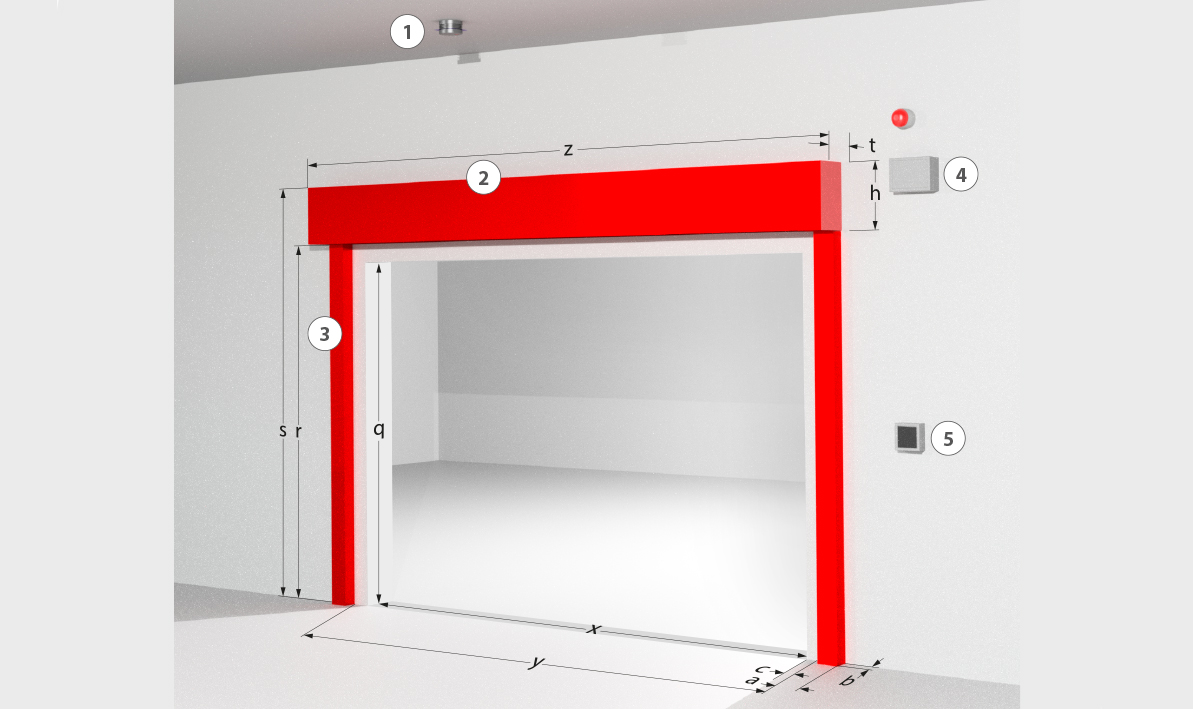
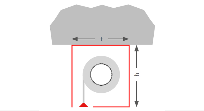
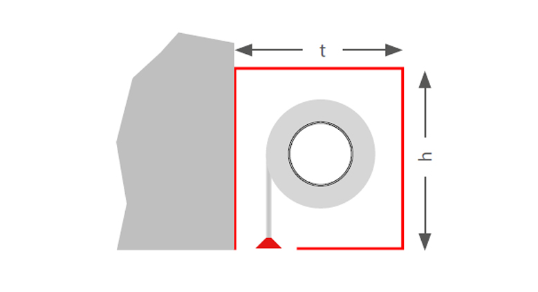
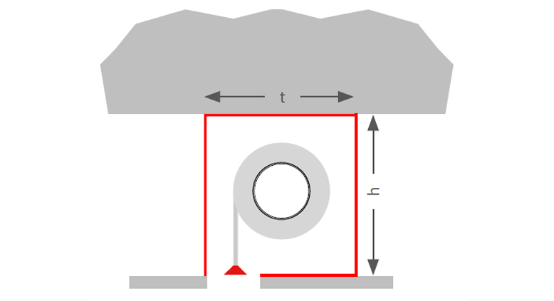
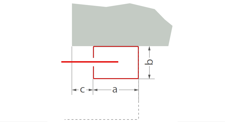
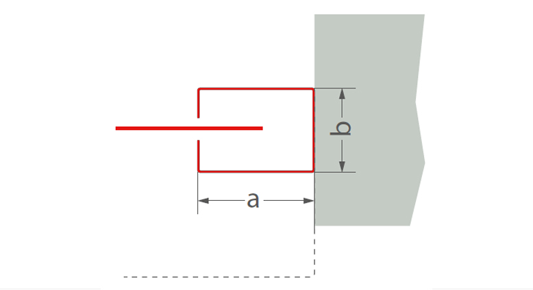
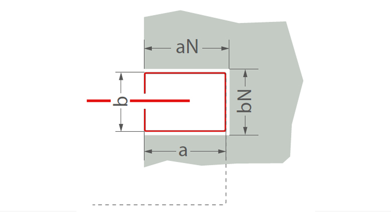
Structural system design (system drawing)

The combination of classifications or the ratio of clear system width to clear system height can reduce the stated maximum dimensions, the dimensions of the winding enclosure and the guide rails can vary. The specifications on the offer apply.

ClassificationFabricSystem width (SB)Drop length (AL)t (mm)h (mm)
E 303350 x 2815Ecotex 1100 A2140Type A, BType 1, 2
E 603350 x 2815Ecotex 1100 A2140Type A, BType 1, 2
E 903350 x 2815Ecotex 1100 A2200Type A, BType 1, 2
EW 303350 x 2815Ecotex 1100 A2140Type A, BType 1, 2
E 306800 x 6800Heliotex140Type A, BType 1, 2
E 906000 x 6000Heliotex200Type A, BType 1, 2
EW 906000 x 6000Heliotex200Type A, BType 1, 2
C06000 x 6000Heliotex
C0, C1, C25880 x 4280Ecotex 1100 A2

The installation situation must comply with the building code requirements of the country of installation. The fire resistance of a ceiling or wall support structure and the adjacent components must at least correspond to that of the fire and/or smoke protection closure/fire and/or smoke protection curtain. Proof of the stability and serviceability of the adjacent walls and components must be provided under general ambient conditions and in the event of fire. See also notes on the standard supporting structure in EN1366-7:2004 or EN1363-1:2020. The fire protection system must not be subjected to any additional loads other than its own weight, even in the event of fire.
* Deviations from size dimensions on request
** Tested wall types according to the installation instructions

Winding case


Deckenmontage
Ceiling mounting
Type A: t = 200 mm, h = 220 mm
Type B: t = 250 mm, h = 260 mm
Wandmontage
Wall mounting
Type B: t = 200 mm, h = 220 mm
Type C: t = 250 mm, h = 260 mm
Deckenmontage Unterdecke
Ceiling mounting suspended ceiling
Type B: t = 200 mm, h = 220 mm
Type C: t = 250 mm, h = 260 mm

Guide rails


Typ 1
Type 1(Wall mounting)
a = 80 mm

b = 60 mm
c ≥ 0 mm
FSV-E-80-KB
Type 2 (Soffit mounting)
a = 80 mm
b = 60 mm
FSV-E-80-KN
Type 2 (Niche mounting)
a = 80 mm
b = 60 mm

aN = 85 mm
bN = 70 mm